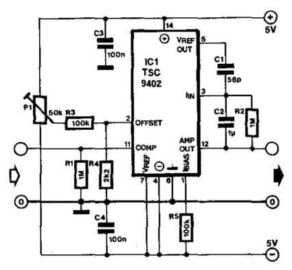
Schematic of the voltage-to-current converter. Frequency converter voltage circuit using ca3130 figure volts eleccircuit input Converter diagram circuit period voltage saving intermittent power build lab
Schematic diagram for the voltage-to-current converter circuit. The
Voltage converter frequency circuit diagram circuits simple requency gr next
Voltage converter negative circuit controlled diagram simple gr next full circuits
Current-to-voltage converter circuit.Simple period-to-voltage converter circuit diagram Converter frequency voltage circuit diagram build circuits output electronicSchematic diagram for the voltage-to-current converter circuit. the.
Simple up-controlled negative voltage converter circuit diagramVoltage dc converter circuits volts nuts magazine Converter voltageCircuit diagram of the current to voltage converter..

12 to 24 volt dc converter circuits
Build a voltage to frequency converter circuit diagram 3230v ac to 12v dc and 5v dc regulated power converter-electron-fmuser 1.5v to 5v boost converter circuit for micro computer220v to 12v dc converter circuit diagram.
Circuit diagram of the proposed converterAnalog to digital converter circuit Voltage to current converter opamp circuit » hackatronicSchematic diagram for the voltage-to-current converter circuit. the.
Voltage converter schematic
What is voltage to current converter (v to i converter) using op-ampConverter voltage schematic vdc Build a voltage-to-frequency converter circuit diagram 2Current to voltage converter circuit.
Converter circuit diagramVoltage to frequency converter circuit diagram Voltage converter opamp rl convertingVoltage converters projects and circuits.

Dc converter circuit diagram step using boost 12v 24v simple 12vdc 24vdc volt voltage 24 power circuits ic output wiring
Diagram voltage circuit converter period simple circuits electronicVoltage converter current circuit diagram simple dc rms circuits ac popular gr next full electronic Voltage to frequency converter circuit using ca3130Shows the circuit diagram for current to voltage converter. the first.
Schematic of the voltage to current converter circuit.Voltage converter circuit diagram frequency ic simple circuits build gr next lab Voltage converter figureCurrent to voltage converter circuit diagram.

Voltage converter circuit diagram
Converter frequency voltage simple diagram circuitCurrent to voltage converter circuit diagram Voltage to current converter circuit diagramCircuit analog converter digital simple schematic diagram using parts components layout pcb projects clock fig eleccircuit.
Converter 5v micro circuit boost dc step computer eleccircuit 12v battery voltage diagram circuits power output electronic convert charger 2vSchematic diagram for the voltage-to-current converter circuit. the Dc voltage converter circuitsSimple frequency.

Voltage dc converter circuit transformer circuits multiplier 250v doubling driven basic figure details nutsvolts secondary
Build a period-to-voltage converter circuit diagramDc voltage converter circuits Dc converter ac circuit voltage diagram power supply circuits converters frequency board converting ic wave into connect projects 70v sineCapacitance to voltage converter circuit diagram..
Voltage frequency converter circuit diagram build .